1. Introduction
This article is a continuation of the Optical Sensing System Design – Optical Elements series. Retroreflectors based on prism geometry are optical components that redirect incident light back toward its source while preserving its optical content, without dispersing it into different wavelengths. If you have not yet read it, you can find the previous article, Part 3C – Optical Elements: Prisms, here.
Due to their frequent use in optoelectronic applications, retroreflectors are discussed here as a separate topic.
2. Operating Principle of Retroreflectors
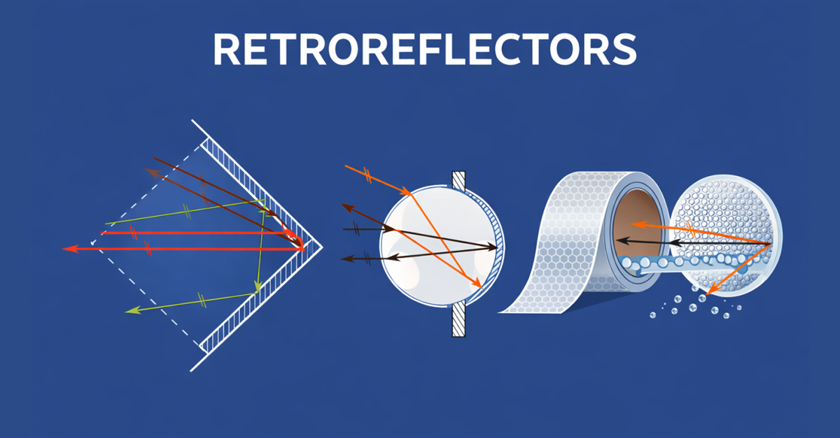
Retroreflectors are optical elements designed to return incident light in a direction close to its original path. Unlike conventional mirrors, they can redirect light back toward its source within a certain acceptance angle, without requiring precise angular alignment. This characteristic makes retroreflectors particularly advantageous in optoelectronic systems where alignment tolerance is critical.
3. Types of Retroreflectors – Functional Classification
Retroreflectors can be functionally classified into different geometries based on the principle by which retroreflection is achieved. This classification is important for understanding the optical structure responsible for the retroreflective behavior.
3.1 Corner-Cube Retroreflectors
Solid glass retroreflectors are commonly referred to as corner-cube retroreflectors. This designation originates from the geometry of the reflective surfaces, which consist of three mutually perpendicular planes forming the corner of a cube. Light entering the reflector undergoes three successive reflections and is redirected by approximately 180°, returning parallel to the incident direction regardless of the entry angle. These retroreflectors can be manufactured from glass or plastic.
3.1.1 Glass Corner-Cube Retroreflectors
In these retroreflectors, retroreflection is achieved with high efficiency through the principle of total internal reflection occurring within the glass material. This structure provides significant advantages, particularly in applications requiring high optical precision.
Detailed technical explanations can be found in the following reference: https://www.thorlabs.com/control-beam-path-through-a-corner-cube-retroflector?tabName=Insights
Applications
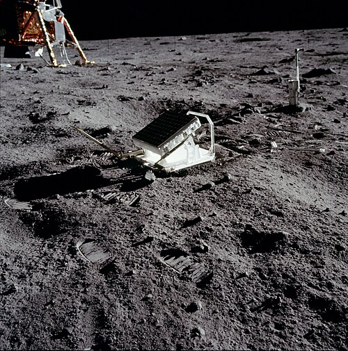
- Distance measurement and laser ranging experiments in space science
- Scientific and laboratory applications requiring high precision
Disadvantages
- High cost
- Fragile structure
- Relatively high weight
3.1.2 Plastic Corner-Cube Retroreflectors
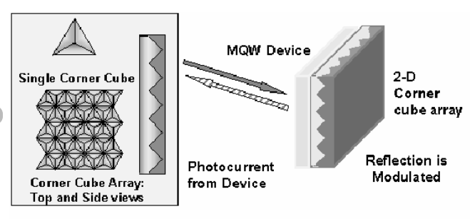
In plastic retroreflectors, the retroreflection effect is achieved through micro- or macro-scale corner-cube (triple-mirror) geometries integrated into the material or its rear surface. These microstructures redirect incident light back toward the source through successive reflections.
Compared to glass-based retroreflectors, plastic retroreflectors are lighter, more economical, and easier to mount. For this reason, they are widely used in industrial sensor applications, automation systems, and mass-produced solutions. Although their retroreflective efficiency is generally lower than that of glass reflectors, their cost advantage makes them attractive for industrial use.
Based on my own experience, small plastic reflectors (e.g., 5 × 5 mm) tend to exhibit more consistent performance. As the size increases—particularly beyond 10 × 10 mm—performance variations due to manufacturing tolerances become more pronounced. In one project, I had the opportunity to compare a large number of reflectors from different manufacturers; unfortunately, only a limited number met expectations in terms of consistency and performance.
Comprehensive information on reflector technologies used in retro-reflective sensors and time-of-flight (ToF) sensor applications can be found at the following link:
https://www.wenglor.com/en/Reflector-and-Reflective-Foil-Technology
3.2 Cat’s Eye Retroreflectors
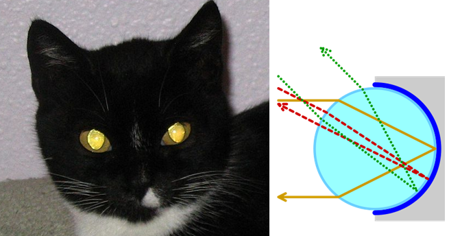
Cat’s eye retroreflectors operate based on a combination of a lens and a reflective surface positioned near the focal point of the lens. Incident light is first refracted and focused by the lens, then reflected by the mirror surface, and finally passes through the lens again, returning toward the source along a direction close to the original path.
Unlike corner-cube retroreflectors, retroreflection in cat’s eye geometries is achieved through the combined use of refraction and reflection. As a result, their performance is directly dependent on the focal length of the lens and the distance between the reflector and the light source.
Cat’s eye geometries provide highly effective retroreflection within a specific operating distance range. When the reflector is positioned close to the designed focal conditions of the lens, the returned beam is strong and well-defined. However, outside this distance range, retroreflective efficiency decreases significantly, making cat’s eye reflectors inherently distance-sensitive.
While corner-cube retroreflectors offer higher tolerance to variations in both incident angle and distance, cat’s eye reflectors are typically preferred in systems with well-controlled geometries.
Interactive ray-optics simulations comparing beam behavior in corner-cube and cat’s eye retroreflectors can be found at the following link. These simulations clearly illustrate the effect of focal conditions on retroreflection in cat’s eye geometries:
https://phydemo.app/ray-optics/gallery/retroreflectors
Applications
- Optical sensing systems with well-defined operating distances
- Laser-based alignment and positioning applications
- Laboratory and experimental optical setups
- Calibration and reference measurement systems
Advantages
- High and stable retroreflection at the correct operating distance
- Predictable optical behavior due to lens-based design
- Compact structure with well-defined beam return
Disadvantages
- Sensitivity to distance and focal conditions
- Narrower acceptance angle compared to corner-cube reflectors
- Greater sensitivity to mechanical misalignment
In practice, cat’s eye retroreflectors are an effective solution in applications where system geometry is well known and operating distance can be controlled. In more variable and demanding industrial environments, corner-cube geometries are generally more advantageous.
4. Retroreflective Foils and Tapes – Geometry and Structure
Although foil- or tape-shaped retroreflectors appear to be single optical elements, they are in fact composed of numerous micro-scale geometries arranged across a surface. In these reflectors, retroreflection is achieved through two primary principles, depending on the type of micro-geometry used.
4.1 Microprismatic (Corner-Cube-Based) Reflective Foils
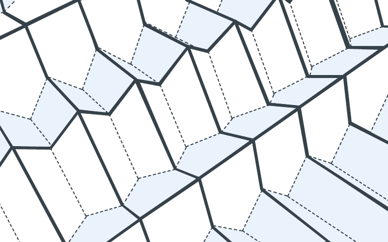
In microprismatic reflective foils, the geometry consists of a large number of micro corner-cube structures formed on the rear surface. Each micro prism operates on the same principle as a conventional corner-cube retroreflector, but at micrometer scale. Incident light is redirected back toward its source through successive reflections within these microstructures.
This design is commonly used in high-performance reflective foils referred to as “diamond grade.” Due to their microprismatic geometry, these foils offer higher retroreflective efficiency than glass-bead-based alternatives.
More detailed information can be found at the following link: https://www.reflecto.shop/useful-knowledge/diamond-grade-dg-reflective-film-from-3m
4.2 Glass Bead (Spherical Bead) Based Reflective Foils
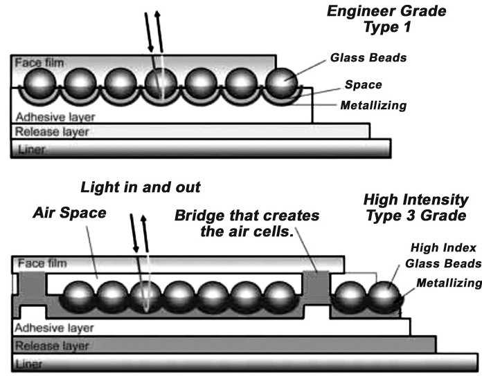
In spherical glass bead retroreflectors, the retroreflection effect is achieved through refraction within the glass bead and reflection from a reflective layer on its rear surface. Each glass bead acts optically like a small lens. Incident light enters the bead, is refracted, reflected from the rear surface, and then exits the bead, returning toward the source.
These retroreflectors are typically not used as individual optical elements, but rather as reflective foils or tapes formed by distributing large numbers of glass beads uniformly across a surface. The objective is not high-precision point reflection, but rather enhanced visibility across a wide area.
Compared to corner-cube-based geometries, spherical glass bead structures are simpler and exhibit lower retroreflective efficiency. The returned light is distributed over a wider angular range. In some applications, however, this characteristic is a desirable feature rather than a disadvantage.
Applications
- Traffic signs and road markings
- Reflective safety and warning markings
- High-visibility reflective tapes and coatings
- Low-precision, visually based detection systems
Advantages
- Visibility from wide viewing angles
- Low production and application cost
- Easy application to flexible surfaces
- No requirement for mechanical alignment
Disadvantages
- Lower retroreflective efficiency compared to corner-cube and cat’s eye reflectors
- Not suitable for long-distance or high-precision optoelectronic measurements
- More diffuse light return
In practice, spherical glass bead retroreflectors are preferred in applications where visibility and detectability are more important than measurement precision. Accordingly, they play a significant role in traffic and safety applications rather than in industrial sensor systems.
Conclusion
This article examined retroreflectors in terms of their operating principles, functional geometries, and practical applications. The fundamental differences between corner-cube, cat’s eye, and spherical glass bead-based retroreflectors were discussed from both theoretical and applied perspectives.
It is evident that retroreflector selection is not limited solely to retroreflective efficiency, but is also directly influenced by parameters such as operating distance, acceptance angle, mechanical tolerances, and environmental conditions. For this reason, retroreflectors—often considered secondary components—play a critical role in measurement reliability and overall system performance in optoelectronic systems.
Return to Part 1 and the complete series reading order.
References
- Hecht, E., Optics, 5th Edition, Addison-Wesley, 2017.
- Thorlabs Inc., Corner Cube Retroreflectors – Principles and Applications. https://www.thorlabs.com/control-beam-path-through-a-corner-cube-retroflector
- Gasvik, K. J., Optical Metrology, 3rd Edition, Wiley, 2002.
- Optical Society of America (OSA), Retroreflection and Optical Design Fundamentals.
- Wenglor Sensoric GmbH, Reflector and Reflective Foil Technology. https://www.wenglor.com/en/Reflector-and-Reflective-Foil-Technology
- Wikipedia contributors, Retroreflector. https://en.wikipedia.org/wiki/Retroreflector
- PhyDemo – Ray Optics Simulator, Retroreflectors. https://phydemo.app/ray-optics/gallery/retroreflectors