
I initially planned to cover all optical elements within a single article. As the writing progressed, it became clear that polarization alone was deep enough to stand on its own. Rather than addressing everything superficially, I chose to expand Part 3 into several focused articles. The previous article, Part 3A – Optical Elements: Lenses, is available here.
1. Introduction – The Knowledge of Letting Go
To move forward, it is sometimes necessary to let go of more than we need. Polarization is one of the clearest optical manifestations of this idea. Instead of using all components of light simultaneously, selecting a specific orientation simplifies the image and makes it more meaningful.
A striking example can be found in nature. Bees are able to navigate by sensing the polarization patterns of the sky, even when the Sun is not visible. What appears uniform to the human eye becomes a structured map carrying directional information for them. By accessing more information from light—not more light itself—the correct information emerges.
For this reason, polarization should not be treated as a secondary detail in camera sensors, biomedical imaging, infrared systems, or three-dimensional (3D) imaging technologies. It is a fundamental tool that deepens the information content of modern optical systems.
2. Physical Meaning of Light and Polarization
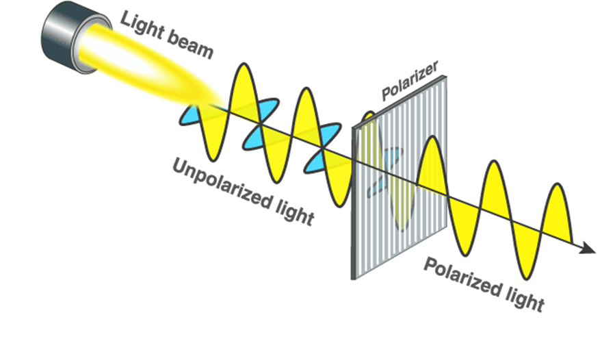
Light is an electromagnetic wave consisting of electric and magnetic field components that oscillate perpendicular to the direction of propagation. In optical applications, polarization primarily refers to the spatial orientation of the electric field vector. This is because the interaction of light with matter, as well as its detection, occurs predominantly through the electric field component.
In natural light sources (such as the Sun, incandescent lamps, and LEDs), the electric field vector assumes random orientations over time. Such light is defined as unpolarized light. Polarization, in contrast, refers to the elimination or controlled organization of this randomness.
3. Types of Polarization
3.1 Linear Polarization
In linear polarization, the electric field vector oscillates along a single direction perpendicular to the direction of propagation. While the field magnitude varies back and forth in time, its orientation remains constant.
This is the simplest and most commonly encountered form of polarization. It is widely used in camera filters and LCD displays, and often serves as the reference polarization state in laser systems.
3.2 Circular Polarization
In circular polarization, the electric field vector rotates with constant magnitude, tracing a circular path over time. This occurs when two orthogonal linear polarization components of equal amplitude combine with a phase difference of 90°.
Circular polarization plays an important role particularly in:
- 3D imaging systems
- The study of optically active (chiral) materials
- Certain sensor and laser applications
3.3 Elliptical Polarization
Elliptical polarization represents the most general polarization state, in which the electric field vector traces an ellipse over time. Both linear and circular polarization can be regarded as special cases of elliptical polarization.
In real optical systems, factors such as alignment errors, wavelength deviations, and imperfections in optical components often result in elliptical polarization rather than ideal linear or circular states. For this reason, elliptical polarization is the most frequently encountered polarization state in practical applications.
The time-dependent behavior of elliptical polarization can be visualized in the following video:
How Light’s Polarization Can Change After Reflecting from a Metal Mirror | Thorlabs Insights
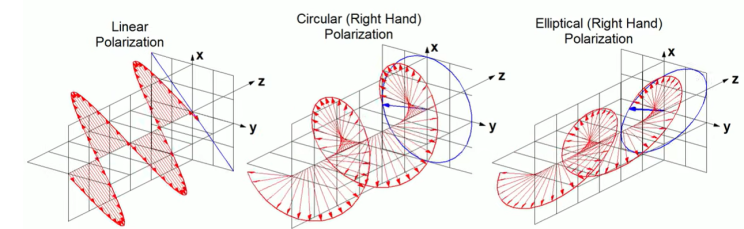
Electric field trajectories corresponding to different polarization states.
Source: Ab Newswire — https://www.abnewswire.com/pressreleases/what-are-circularly-polarized-antennas-and-linearly-polarized-antennas-in-rfid_634829.html
4. Birefringence
In isotropic materials such as glass or water, light propagates identically in all directions. The material responds uniformly to the electric field of the incident electromagnetic wave, resulting in a single refractive index.
Many crystalline materials, however, lack this symmetry. Their internal structure is directionally ordered, causing the interaction between the electromagnetic field and the material to depend on orientation. When light enters such a medium, different components of the electric field interact differently with the crystal lattice.
This direction-dependent optical response is known as birefringence. In a birefringent material, a single incident light wave splits into two distinct waves as it propagates through the crystal.
Physically, birefringence originates from the anisotropic polarization response of the material. The crystal supports different phase velocities for different electric field orientations, leading to direction-dependent refractive indices.
Birefringence is not a secondary effect; it is a fundamental consequence of anisotropy and forms the physical basis of polarization control in optical systems.
What is birefringence used for?
Birefringence enables several fundamental operations in optical design:
- Enables the selective control of polarization states
- Allows the separation of orthogonal polarization components
- Forms the basis of polarization-selective optical systems
This property is essential for the operation of wave plates, polarization beam splitters, and many precision optical instruments.
This anisotropic response does not merely modify light—it defines two distinct propagation modes within the crystal.
5. Ordinary and Extraordinary Rays (o-ray and e-ray)
As light propagates through a birefringent crystal, the medium supports two distinct propagation modes: the ordinary ray (o-ray) and the extraordinary ray (e-ray).
- Ordinary ray (o-ray): The o-ray experiences a refractive index that is independent of the propagation direction. It follows Snell’s law and behaves similarly to light propagating in an isotropic medium.
- Extraordinary ray (e-ray): The e-ray experiences a refractive index that depends on the direction of propagation relative to the crystal’s optical axis. As a result, it does not strictly obey Snell’s law, and its phase velocity varies with direction.
The o-ray and e-ray possess orthogonal polarization states. The crystal separates the incident electric field into two preferred polarization directions, each associated with a different optical response.
This separation is the physical mechanism behind birefringence-based polarization control.
6. Polarizers
Polarizers are optical elements that selectively transmit light with a desired polarization state while suppressing the orthogonal component. This selectivity is often achieved by exploiting birefringence and anisotropic propagation.
When a birefringent crystal is cut at an appropriate angle, the ordinary and extraordinary rays follow different paths within the crystal. Optical design principles are then used to transmit one ray while rejecting the other, typically through total internal reflection or absorption.
As a result:
- The unwanted polarization is removed
- The desired polarization emerges with high purity
This operating principle underlies widely used polarizers such as Glan–Taylor, Glan–Thompson, and Nicol prism designs. Rather than merely attenuating light, polarizers act as information-selective elements that shape and refine optical signals.
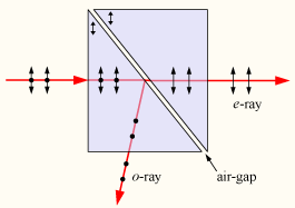
Ray splitting in a birefringent crystal, illustrating ordinary (o -ray ) and extraordinary (e -ray) propagation
Source: https://en.wikipedia.org/wiki/Glan%E2%80%93Taylor_prism
7. The Most Familiar Everyday Application of Birefringence: 3D Movies
One of the most widespread and intuitive applications of birefringence and polarization is 3D cinema technology. In 3D movies, two slightly different images of the same scene are projected simultaneously—one intended for the left eye and the other for the right.
These images are encoded using different polarization states. Thanks to the polarizers embedded in 3D glasses:
- The left eye perceives only the image intended for it
- The right eye perceives only its corresponding image
The human brain then combines these two views to reconstruct a perception of depth. Without precise polarization control, such separation would not be possible, and the 3D effect would collapse into a single flat image.
A detailed visual explanation of this principle can be found in the following video: https://www.youtube.com/watch?v=-SMpGiNVymU
8. Applications of Polarization
Light is not merely a wave; it is also a carrier of information. The way its polarization is organized directly influences what we see—and how we interpret what we see. In modern optics, polarization is not just a physical property; it acts as a key that reveals visual information otherwise hidden.
Below are some areas where polarization plays a critical role today.
Imaging Systems: When Glare Fades, Details Speak
In everyday photography and imaging, reflections and glare often obscure important details. Polarization filters suppress these unwanted components, reducing specular reflections and enhancing true surface features.
A particularly striking example appears in microscopy. Consider an insect embedded in Baltic amber. Under normal illumination, the amber appears largely uniform and opaque. When viewed under polarized light, however, internal stresses within the resin and hidden inclusions become visible through vivid color patterns. This is not merely an aesthetic transformation—it provides direct insight into the physical processes and internal structure of the material.

Laser Systems: Control Becomes Essential
Lasers lie at the heart of modern optical systems. In these systems, polarization control is not optional—it is essential. By carefully managing polarization:
- Energy efficiency is improved
- Noise caused by back reflections is reduced
- Beam stability is enhanced
Crucially, polarization control does not typically reside in the laser source itself, but in the optical systems surrounding it. These elements make laser beams cleaner, more stable, and more reliable, enabling their use in precision sensing, communication, and measurement applications.
Biomedical Optics: Reading Tissue Through Light
Biological tissues demand more than shape-based imaging; they require access to internal structure and organization. Polarized light microscopy reveals oriented structures such as collagen fibers and highlights microstructural features that are otherwise invisible under conventional illumination.
In biomedical imaging, polarization is not merely an added contrast mechanism—it represents a fundamentally different way of seeing tissue. By encoding structural information into measurable optical signals, polarization enables more meaningful interpretation of biological materials.
Polarization microscopy is widely used in materials, earth sciences, and biology to identify materials and minerals based on birefringence and characteristic optical colors. In biological samples, it reveals structured components such as crystals, cellulose, and starch.
Defense and Space Applications: Redefining Vision
In infrared (IR) and near-infrared (NIR) imaging, polarization significantly enhances target-to-background discrimination. Beyond intensity alone, polarization reveals surface properties, material differences, and subtle features that conventional imaging systems often fail to detect.
Techniques such as polarized ring illumination further suppress glare and expose fine surface details, even in harsh or demanding environments. In defense and space applications, polarization expands the limits of vision rather than merely refining it.
Materials Science: Stress, Structure, and the Language of Color
Some of the most striking applications of polarization appear in materials science. Materials that initially seem uniform often reveal internal stresses, microstructural variations, and manufacturing-induced deformations when observed under polarized light.
Photoelasticity provides a clear illustration of this principle:
- Stressed materials exhibit birefringence
- Polarized light renders these stresses visible through characteristic color patterns
In this context, color becomes a language—one that conveys information about internal forces, structural integrity, and material history.
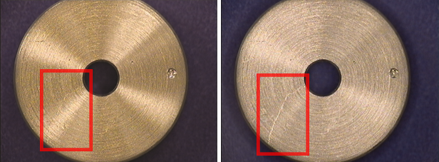
Polarizing the ring light output and the lens sparately can greatly reduce glace effect to reveral important surface detail
Source: Edmund Optics — https://www.edmundoptics.com/knowledge-center/application-notes/illumination/successful-light-polarization-techniques/
Further Reading
More application examples and practical demonstrations of polarization microscopy can be found at: https://www.leica-microsystems.com/science-lab/industrial/the-polarization-microscopy-principle/
9. Conclusion
Polarization is not merely a technical attribute of light; it is a fundamental optical tool that allows information to be isolated and made visible. Through birefringence, prism polarizers, and wave plates, light is guided without force—unnecessary components are removed, and what carries meaning remains.
In this sense, polarization reflects the Taoist concept of Wu Wei: gaining more not by adding, but by removing what is unnecessary. It does not multiply light; it simplifies it—revealing structure, contrast, and information that would otherwise remain hidden.
For this reason, polarization is not only a cornerstone of advanced optical systems, but also an integral part of the design mindset for anyone working with light.
Continue with Part 3C – Optical Elements: Prisms.
References and Image Credits
This article is based primarily on Handbook of Optics, Second Edition, Volume II, edited by M. Bass, along with selected application notes and educational material from the Edmund Optics Knowledge Center.