Introduction
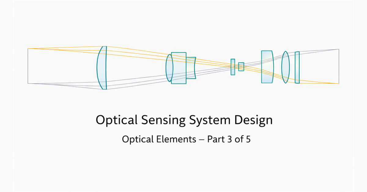
This article begins Part 3 of the optical sensing system design series. The subject of optical elements proved too broad for a single article, so Part 3 was expanded into focused articles on lenses, polarization, prisms, and retroreflectors. You can read Part 2 – Transmitter & Receiver Selection here.
Although my formal academic background is not directly rooted in optics, optical elements that guide and manipulate light have long been of particular interest to me, leading naturally toward optoelectronics and practical optical system design. Given the breadth of the subject, this work focuses specifically on lenses, one of the most fundamental optical elements, while other components will be addressed in subsequent parts of the series.
To enhance clarity and accessibility, the discussion is supported by visual illustrations and selected video resources. Alongside theoretical considerations, practical insights gained from working with real optical systems are also shared.
What Is an Optical Lens?
Optical lenses are refractive optical elements designed to focus or diverge light. They may consist of a single optical element or multiple elements combined into a compound lens system.
The primary function of a lens is to control the direction and spatial distribution of light rays in order to achieve the desired imaging or light-transmission conditions.
Basic Terminology
1. Divergence
Divergence describes how rapidly a light beam spreads angularly after leaving its source. As the beam propagates, its diameter increases; the larger the divergence, the faster this expansion occurs.
- High divergence → optical power density decreases rapidly with distance
- Collimation quality is directly related to divergence
- Long focal-length lenses reduce divergence, while short focal-length lenses increase it.
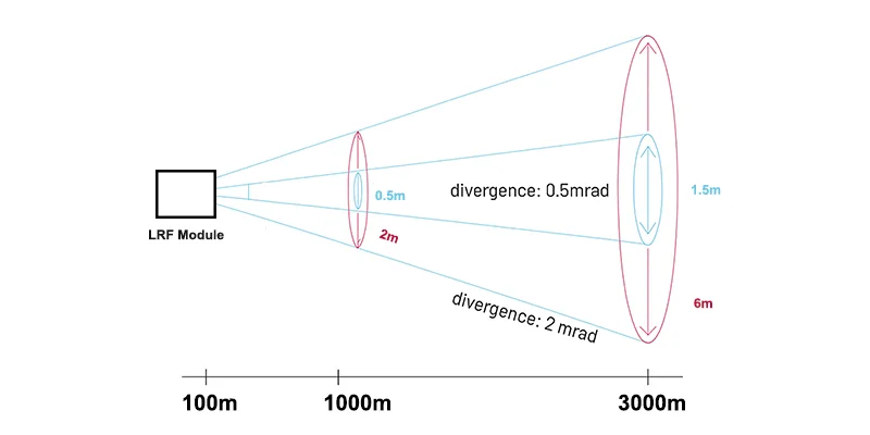
Source: Adapted from typical LRF beam-divergence specifications.
2. Numerical Aperture (NA)
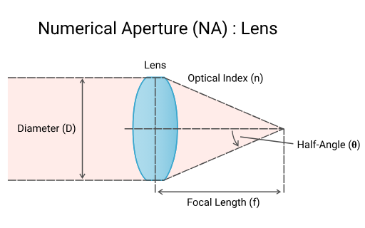
The numerical aperture (NA) is a fundamental optical parameter that defines how much light a lens can collect and over what range of angles. It plays a critical role in laser collimation, light collection, and resolution calculations.
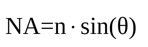
Lenses with a high numerical aperture enable higher light intensity and smaller spot sizes. However, this also increases the risk of optical aberrations and makes system design more sensitive and challenging.
Source: Adapted from standard laser-beam divergence geometry.
3. Diopters
The optical power of a lens increases as its focal length decreases. The diopter is a numerical representation of this relationship:
- 1 diopter → focal length of 1 m
- 2 diopters → focal length of 0.5 m
- 5 diopters → focal length of 0.2 m
4.Field of View (FOV)
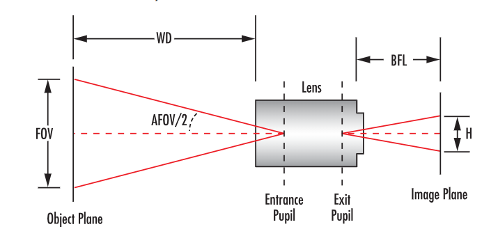
The field of view (FOV) defines the physical area that can be observed or imaged by a lens system.
5. Working Distance (WD)
The working distance (WD) is the distance between the lens and the object plane in an optical system. It specifies how far the object must be from the lens in order to achieve sharp focus.
Source: Edmund Optics.
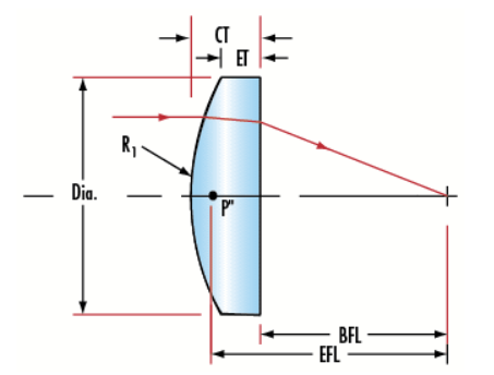
6. Effective Focal Length (EFL)
- Represents the true optical power of the lens
- Measured from the principal plane
- The primary focal length used in optical system design
7. Back Focal Length (BFL)
- Distance from the rear surface of the lens to the focal point
- Critical for sensor placement
- EFL ≠ BFL for thick lenses
Source: Edmund Optics.
Lens focal length is generally specified as EFL. To determine sensor placement, the BFL value must be used.
Focal length is wavelength-dependent; the operating wavelength must always be considered when positioning the sensor.
You can use the following link for calculations. I also recommend you check out many useful pieces of information.
https://www.edmundoptics.com/knowledge-center/?Query=&CategoryId=&Filters=techTool
The following video resources are provided to support the discussion and offer additional visual insight into lens behavior and design principles.
https://www.youtube.com/watch?v=37H5jJmHh2Y
Optical Aberrations
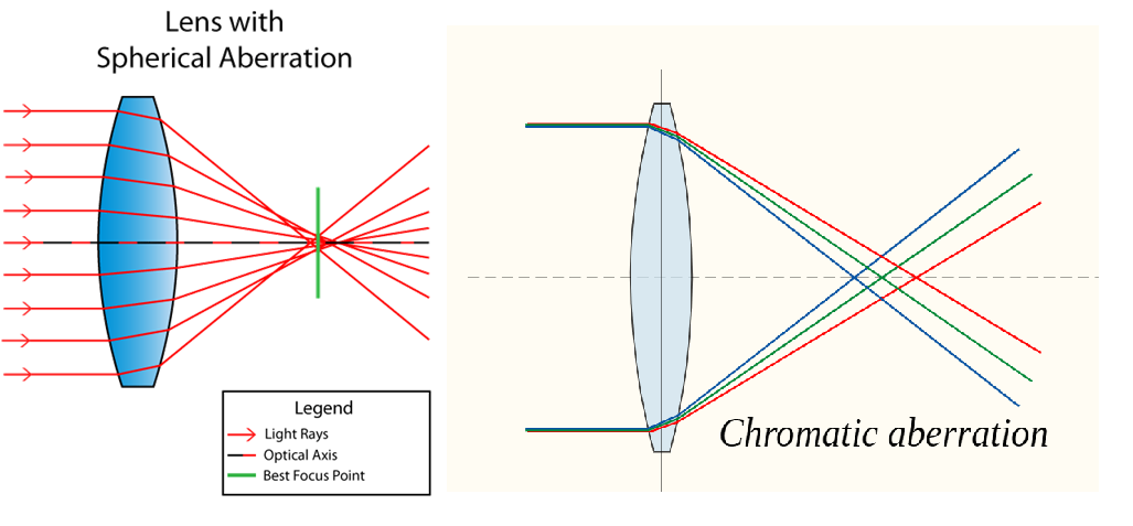
Spherical Aberration
Rays passing through the edges of a spherical lens do not focus at the same point as rays passing through the center. This reduces image sharpness and becomes more pronounced at high numerical apertures.
Chromatic Aberration
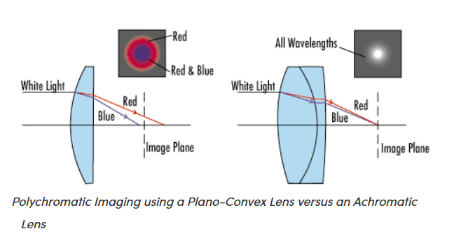
In single-material lenses, different wavelengths refract by different amounts. As a result, blue and red light focus at different points.
These effects limit the suitability of simple spherical lenses in high-precision applications.
The video below explains aberration very well and also why Canon lenses are so good.
https://www.youtube.com/watch?v=EL9J3Km6wxI
Source: Wikimedia Commons.
Spherical Lenses: The Fundamental Building Blocks of Optics
Spherical lenses are optical elements whose refracting surfaces are portions of a sphere. In these lenses, the surface curvature does not vary with distance from the optical axis; in other words, it remains constant at every point.
This simple geometric structure has made spherical lenses some of the oldest and most widely used components in optical design.
Principle of Operation
Spherical lenses redirect light by refracting it at their surfaces in accordance with Snell’s law. The curvature of the lens and the refractive index of the material together cause the light to:
- converge (focusing behavior), or
- diverge (diverging behavior).
This process is entirely explained by geometrical optics.
Subtypes of Spherical Lenses and Their Usage Rationale
In optical design, the direction from which light enters a lens is of great importance. For this reason, spherical lenses are divided into different subtypes based on their surface geometries:
Spherical Lens Types
1. Plano-Convex Lenses
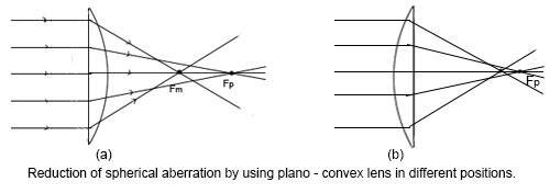
Plano-convex lenses have one flat surface and one convex surface. When collimated light enters through the flat surface and exits through the convex surface:
- Minimal refraction occurs at the first surface
- The main refraction happens at a single spherical surface
- The difference between marginal and central rays is reduced
This configuration minimizes spherical aberration in collimation-to-focus applications. When used in the reverse direction, spherical aberration increases significantly. Therefore, performance strongly depends on the direction of light propagation.
Source: Principles of Physics XI, Optics – Spherical Aberration.
2. Bi-Convex Lenses
Bi-convex lenses have two outward-curving surfaces and focus parallel rays to a single focal point. Their symmetrical geometry distributes refraction evenly across both surfaces, making them suitable for systems where object and image distances are similar.
They are widely used in cameras and microscopes. However, for collimated light and high-NA applications, bi-convex lenses may introduce increased spherical aberration compared to alternative geometries.
3. Bi-Concave Lenses
Bi-concave lenses have two inward-curving surfaces and a negative focal length. They cause parallel light rays to diverge, behaving as if the light originates from a virtual focal point.
These lenses are commonly used for beam expansion, divergence control, and optical path compensation in laser systems, projection systems, and optical communication modules.

Source: Math/Science Nucleus.
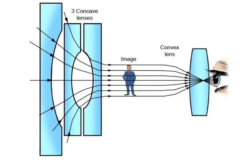
4. Plano-Concave Lenses
Plano-concave lenses consist of one flat surface and one concave surface. They diverge incoming parallel light and are used for beam expansion, divergence control, optical correction, and signal routing in fiber-optic systems.
Source: Adapted from standard geometrical-optics ray diagrams.
Inherent Limitations of Spherical Lenses: Aberrations
The most fundamental disadvantage of spherical lenses is optical aberrations, which are a direct consequence of their surface geometry.
Special Lens
1. Aspheric Lenses
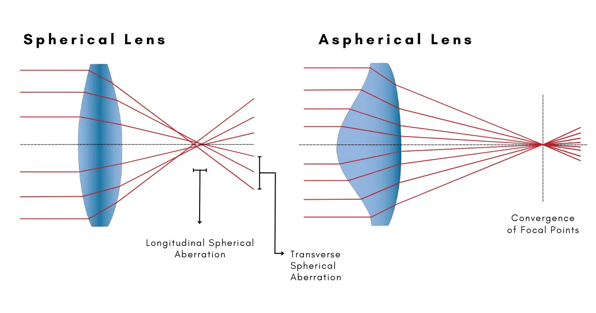
Aspheric lenses have at least one non-spherical surface. Unlike spherical lenses, their curvature varies with distance from the optical axis, allowing central and marginal rays to focus at the same point.
As a result, aspheric lenses provide:
- Reduced aberrations
- Smaller spot sizes
- Higher resolution
They are widely used in laser collimation, fiber coupling, and high-NA optical systems
Source: EKSMA Optics.
Supplementary video materials are provided below for further reference.
https://www.youtube.com/watch?v=twMMPwKdWMc
https://www.youtube.com/shorts/4KxPaf3GFrw
2. Fresnel Lenses
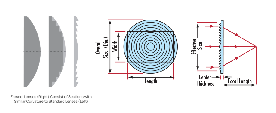
A Fresnel lens preserves the focusing power of a conventional lens while significantly reducing thickness and weight. This is achieved by dividing the lens surface into concentric stepped rings, each acting as a small prism.
Advantages
- Lightweight and thin structure
- Suitable for large-aperture systems
- Efficient for illumination and light collection
Disadvantages
- Diffraction effects and surface artifacts
- Limited image quality
Fresnel lenses are preferred for light-guiding applications rather than high-quality imaging.
Source: Thorlabs and Edmund Optics.
3. Achromatic Lenses
Achromatic lenses are multi-element lenses, typically consisting of one positive and one negative element made from different glass types. By exploiting differences in dispersion, two wavelengths are brought to the same focal point, significantly reducing chromatic aberration.
They are essential in white-light imaging systems.
A supplementary video illustrating Fresnel lenses is provided below.
https://www.youtube.com/watch?v=pNOGMfmti4w
Source: Edmund Optics.
I’m including an explanatory video about achromatic lenses at the following link:
https://www.youtube.com/watch?v=uloNSzBIaKU
Example Application: Light Collimation
At the end of this article, I briefly touch on the concept of collimation, often referred to in practice as “sending light to infinity.” The video below provides a clear, hands-on summary of the key concepts discussed throughout the article.
From my own experience, I’ve observed that functional collimation setups can be built using Thorlabs components even without advanced optical design expertise. In this sense, the technical resources offered by manufacturers such as Edmund Optics and Thorlabs are extremely valuable references for creating simple yet effective optical designs.
The term “infinity” here does not represent a physical ideal, but rather light that is collimated within acceptable divergence limits for practical applications. The main objective in such systems is to select the smallest possible divergence angle based on the transmission distance and the target illumination area. This approach allows the beam to propagate in a more controlled manner over distance, leading to more efficient and predictable illumination.
https://www.youtube.com/watch?v=z_n7GKdTt0Q&t=41s
Conclusion
This work examined commonly used lens types in optical sensing systems, emphasizing their operating principles, advantages, and practical implications. In practice, lens geometry and placement often exert a greater influence on overall system performance than theoretical calculations alone.
While selecting an appropriate lens is essential, proper implementation and integration ultimately determine the achievable system performance.
Continue with Part 3B – Optical Elements: Polarization.
🐈⬛Finally, I would like to thank the lenses that helped shape my perspective.
References
[1] Edmund Optics, Knowledge Center – Imaging and Lens Fundamentals (link).
[2] Thorlabs, Optical Systems and Lens Tutorials (link).
[3] CLZ Optics, Why Do Plano-Convex Lenses Reduce Spherical Aberration? (link).
[4] EKSMA Optics, Aspherical Lenses – Technical Overview (link).
[5] Edmund Optics, Why Use an Achromatic Lens? (link).
[6] Math/Science Nucleus, Convex and Concave Lens Optics (link).
[7] Principles of Physics XI, Optics – Spherical Aberration.