Why Many Small Openings Can Perform Better Than One Large Aperture
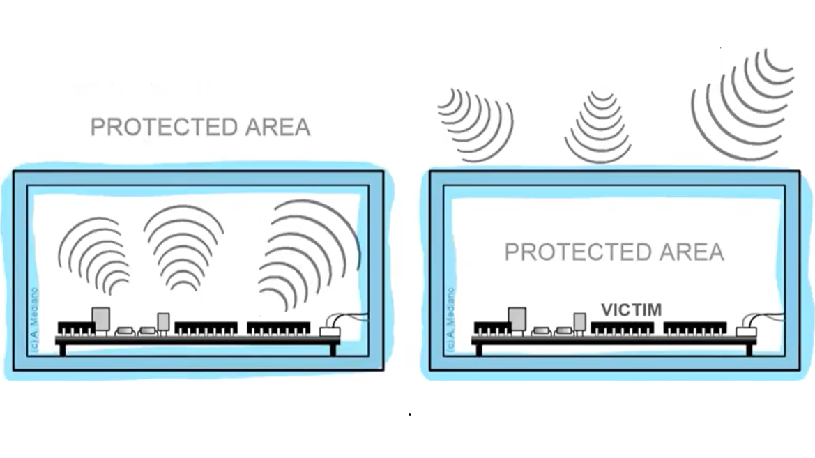
In my earlier EMC articles, I discussed how slots, seams, and cable exits interrupt the continuity of a Faraday cage and can become unintended radiation paths. The companion article The Effect of Slot Openings in a Faraday Cage on EMC examines that enclosure-level problem, while Electromagnetic Shielding Design Tips explains how field type, frequency, conductivity, permeability, and skin depth influence the shielding strategy.
Those principles lead to an important practical question: what can we do when an opening cannot simply be removed? Real electronic products need ventilation for cooling, cable and connector exits for electrical interfaces, display openings, and service access. A completely closed metal enclosure may offer excellent shielding in theory, but it is rarely a workable product architecture.
The goal is therefore not to make every opening disappear. It is to engineer the opening so that it preserves the required function while minimizing electromagnetic leakage. For this compromise, we can take inspiration from nature. A honeycomb uses many small, efficient cells to provide a large overall passage while retaining a strong, organized structure. The same geometry can turn a large uncontrolled aperture into a controlled array of short conductive channels.
From an EMC point of view, the important parameter is not simply the total open area. The dimensions of each individual opening relative to wavelength, its geometry, its depth, and the quality of the surrounding electrical bond all influence the coupling path.
A useful first design question is therefore not:
How much open area do I have?
but rather:
What is the largest electrically significant aperture, and how does it behave at the highest frequency of concern?
From One Large Opening to Many Small Cells
Ventilation creates an obvious design conflict:
- Thermal design wants airflow.
- EMC design wants electrical continuity.
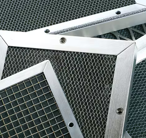
A honeycomb ventilation panel addresses this conflict by dividing one large opening into a large number of small conductive cells.
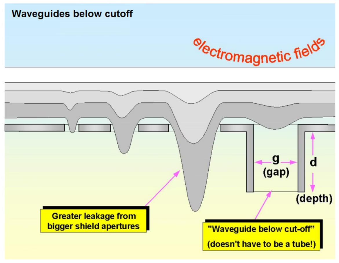
The benefit is not simply that the holes are smaller. Each cell has a finite length, so it behaves approximately like a short metallic waveguide.
When the frequency of interest is below the cutoff frequency supported by the cell geometry, the field does not propagate through the channel as it would through an unrestricted aperture. Instead, it becomes evanescent and decays along the depth of the cell.
This is the basis of the waveguide-below-cutoff concept used in EMC ventilation panels.
Why Cell Size and Depth Matter
The shielding performance of a honeycomb vent depends strongly on geometry.
Two tendencies are especially important:
Smaller cell dimension → higher cutoff frequency
Greater cell depth → greater below-cutoff attenuation
A First-Order Cutoff Estimate
For a rectangular waveguide, the dominant TE₁₀ mode is often used as a first-order estimate:
where a is the largest cell dimension and c is the speed of light. Honeycomb cells are not perfect rectangular waveguides, so this relation is an engineering estimate rather than a product-level qualification equation.
Below cutoff, the idealized attenuation constant can be written as:
where f is the operating frequency and L is the cell depth. For example, a 10 mm characteristic cell dimension gives an approximate cutoff near 15 GHz. At 1 GHz with a 40 mm depth, the ideal single-cell estimate is very high; real panel performance will be lower because of finite conductivity, fringing, seams, gasket contact, manufacturing tolerances, and the surrounding enclosure.
This explains why commercial honeycomb vent designs specify both the cell size and the panel thickness rather than only the total ventilation area.
TE Connectivity describes honeycomb vents as a series of conductive tubes acting as waveguides and notes that tube length should be several times the cell diameter for useful attenuation. MAJR Products similarly describes a 4:1 opening-to-depth ratio as a practical configuration for obtaining waveguide-below-cutoff attenuation while maintaining airflow.
These ratios are useful design guidance, but they should not be treated as universal shielding equations. Final shielding effectiveness depends on the complete mechanical and electrical assembly.
The Honeycomb Is Only as Good as Its Chassis Bond
One of the most important practical points is easy to overlook:
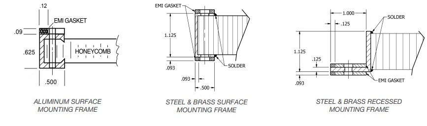
A high-performance honeycomb core can still perform poorly if the frame is badly bonded to the enclosure.
The perimeter of the vent should form a low-impedance electrical connection to the chassis. Paint, anodized surfaces, corrosion, loose fasteners, insufficient contact pressure, or an incorrectly selected gasket can introduce discontinuities around the panel.
At high frequency, those discontinuities may become significant leakage paths themselves.
So the design question is not only:
What cell size should I use?
It is also:
How continuously and how effectively is the entire vent frame bonded to the chassis?
This is why commercial EMI vent assemblies often combine:
- a conductive honeycomb core,
- a rigid conductive frame,
- conductive surface treatment,
- an EMI/RFI gasket,
- and a mechanically controlled mounting interface.
Honeycomb Does Not Make an Opening “Invisible”
Honeycomb structures are effective, but they do not create infinite attenuation.
Real shielding effectiveness depends on several interacting parameters:
- frequency,
- cell size and geometry,
- cell depth,
- material conductivity,
- plating or surface finish,
- field polarization,
- frame design,
- gasket construction,
- contact pressure,
- corrosion,
- and installation quality.
The polarity of the incident field can also matter. In practical honeycomb structures, manufacturing direction and cell construction may produce different shielding performance for different field orientations. This is one reason some manufacturers use crossed or orthogonally oriented honeycomb layers when higher performance is required.
The correct engineering statement is therefore not:
Honeycomb blocks EMI.
A better statement is:
A properly dimensioned and correctly bonded honeycomb structure allows ventilation while forcing electromagnetic coupling through a controlled array of below-cutoff conductive channels.
A Practical EMC Design View
When evaluating a honeycomb ventilation panel, I would consider the following parameters together:
- Highest frequency that must be shielded
- Individual cell dimension
- Cell depth
- Material conductivity
- Surface treatment or plating
- Frame-to-chassis bonding
- EMI gasket design
- Required airflow and pressure drop
- Environmental conditions and corrosion risk
- Required system-level shielding effectiveness
The honeycomb core is therefore only one part of the shielding system.
The complete structure is:
enclosure + honeycomb core + frame + gasket + chassis bond
For good EMC performance, these elements must behave electrically as one continuous shielding structure.
That is what turns a necessary ventilation opening from an uncontrolled EMC weakness into a deliberately engineered electromagnetic path.
Choosing Honeycomb, Mesh, or a Solid Shield
Honeycomb is a strong option when a design needs substantial airflow and a controlled aperture depth. A conductive mesh can be preferable when the available depth is very small or when optical transparency is important, although its shielding performance depends strongly on wire diameter, pitch, and contact to the frame. A solid shield remains the most predictable choice when ventilation is not required or when the lowest possible leakage is the priority.
In practice, the decision should be made with the thermal and EMC requirements together. A panel that meets a shielding target but causes excessive pressure drop is not a successful system design, and a panel that moves enough air but has a poor perimeter bond will not deliver its theoretical shielding performance.
Related Article
For the effect of ordinary slots and apertures on enclosure shielding, see:
The Effect of Slot Openings in a Faraday Cage on EMC
References
- Würth Elektronik, EMC Shielding – A Practical Guide.
- Henry W. Ott, Electromagnetic Compatibility Engineering, Wiley.
- Clayton R. Paul, Introduction to Electromagnetic Compatibility, Wiley.
- TE Connectivity / Kemtron, EMI Vent Panels — Optimizing Airflow and Shielding.
- MAJR Products, Honeycomb Waveguide Panels — EMI/RFI Shielded Vent Panels, 3000 Series.
- MTC, Honeycomb Vent Panels — Flange Profile for EMI/RFI Shielding.
- Hemming, Applying the Waveguide Below Cut-off Principle to Shielded Ventilation Structures.