
Introduction – EMC Tests (Part 2 / 3)
This article is the second part of our three-part series: “Preparing a Product for the Market: CE, EMC and LVD Testing & Certification Guide.”
In Part 1, we covered:
- The real meaning of the CE marking
- RoHS compliance
- The scope of the EMC and LVD Directives
- How a product is classified under these directives
- Which tests are required before market placement
This week, we move into the core of the compliance process and take a deep dive into EMC testing.
What This Part Covers
Scope note: The exact test plan is product-specific. It depends on the applicable harmonized product or generic standard, the product’s ports and power architecture, and its intended residential, commercial or industrial environment. The examples below are representative guidance, not a universal CE test list.
In this section, we will:
- Clearly distinguish EMC and EMI
- Explain the types of EMC standards
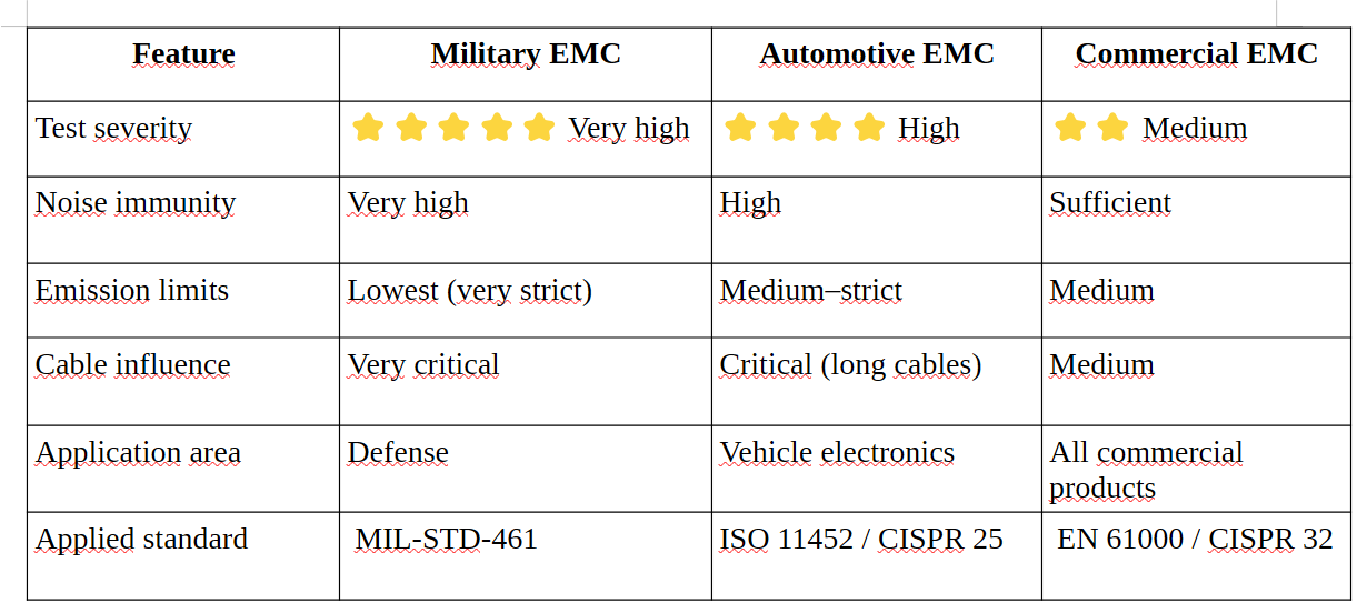
- Compare military, automotive, and commercial EMC standards
- Focus specifically on EMC tests applied to commercial (civil) products
If you’re ready, let’s step into the detailed world of electromagnetic compatibility requirements.
1. EMC Tests and Their Classification
EMC verifies whether a device can operate electromagnetically compatible with its environment.
The objective is simple but critical:
- The device must not emit excessive electromagnetic noise
- The device must not be affected by electromagnetic noise in its environment
2. What Is EMI? (Electromagnetic Interference)
EMI refers to unwanted electromagnetic disturbances that cause devices to interfere with each other.
Every EMI problem consists of three fundamental elements:
- Source → The circuit generating the noise
- Coupling path → The medium that carries the noise
- Victim → The circuit affected and malfunctioning
The purpose of EMC testing is to identify and control this interaction before the product reaches the market.
3. Where Does the “61000” Standard Come From?
The IEC 61000 series, published by the International Electrotechnical Commission (IEC), provides the main framework for EMC phenomena, environments and immunity test methods. Emission limits and product-specific requirements are defined by separate CISPR, product-family and generic standards.
Typical examples include:
- IEC 61000-4-2 → ESD (Electrostatic Discharge)
- IEC 61000-4-3 → Radiated Immunity
- IEC 61000-4-4 → EFT / Burst
- IEC 61000-4-5 → Surge
But what does “61000” actually represent?
The 61000 family is the official IEC EMC standard framework, and all EMC tests are defined within its subparts:
- 61000-1-x → General principles and terminology
- 61000-2-x → Electromagnetic environment definitions
- 61000-3-x → Harmonics and flicker (mains compatibility)
- 61000-4-x → Immunity test methods (ESD, EFT, Surge, RF Immunity, etc.)
- 61000-6-x → Generic standards (residential / industrial environments)
3.1 What Is the Difference Between CISPR and IEC 61000?
CISPR is a separate technical committee within the IEC that focuses exclusively on emission tests.
CISPR standards define how much electromagnetic noise a device is allowed to emit.
Examples include:
- CISPR 32 → Radiated and conducted emissions
- CISPR 14 → Household appliance emissions
- CISPR 25 → Automotive emissions
Short Summary
- CISPR → Emission limits (How much noise can you generate?)
- IEC 61000 → Immunity tests and EMC methodology (How much noise can you tolerate?)
4. Military – Automotive – Commercial EMC Standards
4.1 Military (MIL-STD-461)
MIL-STD-461 includes some of the strictest EMC requirements in the world. It is used for equipment operating in extreme environments such as:
- Radar systems
- Jammers
- Military avionics
4.2 Automotive (ISO 11452, ISO 7637, CISPR 25)
Automotive EMC standards are more demanding than commercial ones because vehicle wiring behaves like an antenna.
They include:
- High RF field levels
- Transients
- Load dump events
4.3 Commercial (CE – EN / CISPR)
These standards apply to residential, office, and industrial products. They are the main focus of this article series.
4.3.4. Summary Comparison of the Three Categories
5. Focus of This Article Series: Commercial EMC
Although understanding military and automotive EMC standards shows how broad the EMC field is, our objective is to introduce the commercial EMC tests commonly considered during CE conformity assessment.
For this reason, in the following sections we will focus only on:
- EN / CISPR emission limits,
- IEC 61000-4-x immunity tests,
- EMC tests that may apply to a CE-marked product, depending on its product standard and interfaces
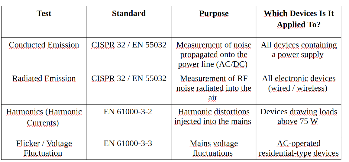
5.1. Emission Tests
5.2. Immunity Tests
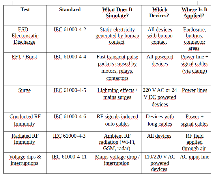
While emission tests measure the noise emitted by the device into the environment, immunity tests verify how resistant the device is to electromagnetic stresses present in the environment.
The table below summarizes what immunity tests are, why they are performed, and which devices they are applied to.
5.2.1 Summary of Immunity Tests
6. Emission Tests – Detailed Test Descriptions
6.1 Conducted Emission
It is the test that measures the RF noise propagated onto the device’s power line.
6.1.1 Which devices is this test applied to?
Applied devices:
- All devices powered from the mains (230 V AC)
- Products with DC input but using an external AC/DC adapter
Not applied devices:
- Battery-powered products (as long as they are not connected to the mains)
- Completely passive devices (sensor elements, cables, connectors, etc.)
6.1.2 Purpose of the Test
- To prevent the device from injecting excessive noise into the mains line
- To prevent malfunction of other devices connected to the same line
- To control high dv/dt noise sources such as SMPS and motor drivers
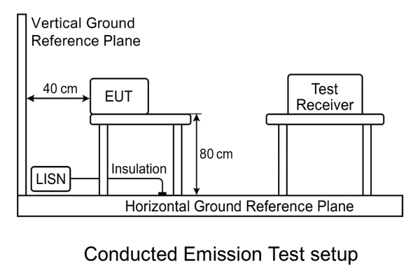
LISN (Line Impedance Stabilization Network) It is connected between the device and the power line; it stabilizes the line impedance and transfers the noise conducted by the EUT to the measuring instrument.
EUT (Equipment Under Test) It is the product being tested.
Ground Reference Plane It is a large metal surface used to establish a common reference in all EMC measurements. In this way, test results are ensured to be the same in every laboratory.
6.1.3 Pass / Fail Criteria
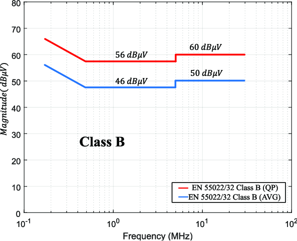
Measured dBµV value:
👉 Must be below the CISPR limit curve.
6.1.4 What Is the CISPR Limit Curve?
The CISPR limit curve is a graphical limit line that shows the maximum amount of noise a device is allowed to emit at each frequency during an emission test.
6.2 Radiated Emission
6.2.1 Purpose of the Test To measure the electromagnetic energy radiated into the air by the device acting like an antenna.
Test frequency range: 30 MHz – 1 GHz (up to 6 GHz when required)
Applied standard:
CISPR 32 / EN 55032
6.2.2 Which Devices Is It Applied To?
Applied:
• All devices that contain electronic circuits and generate electromagnetic radiation during operation
Not applied:
• Passive products that do not generate EMI, such as cables, buttons, connectors, etc.
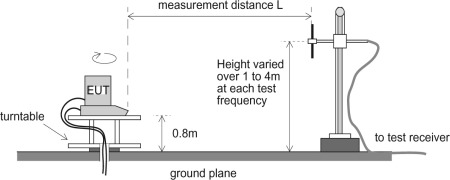
6.2.3 Test Setup
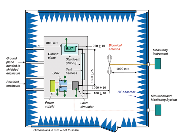
• The test is performed inside an anechoic chamber.
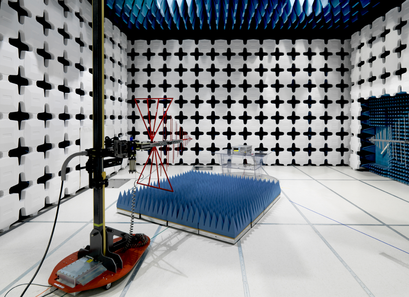
What Is an Anechoic Chamber?
An anechoic chamber is a special test room designed to prevent electromagnetic waves from reflecting off the walls. Thanks to the RF absorbers on the walls, reflections that could occur during measurements are eliminated, and the true radiated emission level of the device is measured.
What Is Inside an Anechoic Chamber?
• Cones (absorbers) on the walls and ceiling that absorb electromagnetic waves
• Rotating turntable
• Receiving antenna with adjustable height
• 3 m or 10 m test distance
• Ferrite-tiled floor
• RF-shielded door
Why Is It Necessary?
When measurements are performed in a normal room:
• Reflections occur from the walls
• The antenna cannot measure the true value
• The measurement may deviate by 10–20 dB and the report becomes invalid
An anechoic chamber, on the other hand, is a “radio dark room.” Instead of light, it absorbs and eliminates RF waves, ensuring that measurements are performed accurately.
6.2.4 Pass / Fail Criterion
The total radiated emission level must be below the limit curve.

Why Is Radiated Emission Testing Performed at Different Distances Such as 3 m and 10 m?
The reason is that electromagnetic waves attenuate with distance according to the 1/r law. Standards define different test distances in order to evaluate how much noise a device will emit into its environment in real-life conditions.
The distance selection is made according to the following criteria:
1) Size of the product
• Small devices → 3 meters
• Large machines → 10 meters or 30 meters (As the device size increases, antenna behavior changes.)
2) Requirements of the test standard
Example: CISPR 32 radiated emission
• Small and medium-sized products → 3 m
• Professional equipment → 10 m
3) The distance that is critical from a regulatory perspective
If space is not an issue, laboratories generally use 10 m, because 10 m measurements are closer to real-world conditions.
Short Summary
• 3 m: Small products, compact chambers
• 10 m: More realistic and safer measurement, large products
• 30 m: Military and special applications
6.3 Harmonic Current Test
6.3.1 Purpose of the Test
Ideally, the AC mains should be a pure 50 Hz sine wave. Some devices draw current not in a sinusoidal form but in a distorted manner. These distortions generate harmonic currents.
When harmonic currents increase:
• Mains transformers heat up
• The neutral line becomes overloaded
• Energy efficiency decreases
For this reason, the EN 61000-3-2 standard defines limits for the harmonic currents injected into the mains by devices.
6.3.2 Which Devices Is It Applied To?
• All AC-powered devices are subject to harmonic testing.
• DC devices are included in this test only if they draw high AC current from the mains (for example, SMPS above 75 W).
6.3.3 Test Environment and Equipment
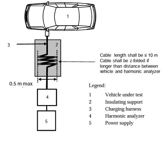
6.3.4 Pass / Fail Criterion Each individual harmonic component of the current drawn from the mains by the device must be below the limits specified in the EN 61000-3-2 standard.
Example
Let us assume that the limit for the 3rd harmonic is 2.30 A. If the measured 3rd harmonic current of the device is 1.10 A, it passes. If the measured 3rd harmonic current of the device is 2.80 A, it fails.
The same evaluation is performed separately for all harmonics.
6.4 Flicker Test
6.4.1 Why Is It Performed? Some devices draw sudden and repetitive current from the mains during operation. This may cause visible flickering of lights in the home, unstable operation of other devices connected to the same line, and degradation of user comfort.
The fundamental question of the flicker test is: Does this device cause visible light flicker on the mains?
6.4.3 Which Devices Is It Applied To?
Devices operating with AC current below 16 A are subject to the flicker test. The flicker test is not applied to devices operating with AC current above 16 A and to DC devices.
6.4.4 Pass / Fail Criterion
The device passes the flicker test if the voltage fluctuations remain below the EN 61000-3-3 limit curves, meaning that the flicker level does not reach visible light flicker.
Example: Let us assume that the limit for the 3rd harmonic is 2.30 A.
Measured value 1.10 A → Pass Measured value 2.80 A → Fail
That’s it.
7. Immunity Tests – Detailed
Performance Levels Used in Immunity Tests In immunity tests, the behavior of the product is classified according to A, B, C, and D performance levels.
Level A: The product operates normally and without errors throughout the test. This is the ideal and fully accepted behavior in all cases.
Level B: Short-term deviations may occur, but the device returns to normal operation automatically after the test. It is accepted as long as there is no permanent effect.
Level C: The product requires a reset to return to normal operation after the test. This level is accepted for household electronics, office equipment, and some industrial products.
It is not accepted for the following products:
- Fire detection systems
- Medical devices
- Safety and defense equipment
- Automotive safety functions
Level D: The product malfunctions, locks up, shuts down, or is damaged. This level is not accepted in any product category.
7.1 ESD Test – IEC 61000-4-2
Test Definition It is a test that evaluates resistance to electrostatic discharge.
7.1.1 Purpose of the Test In daily life, humans carry static electricity in the range of 2 to 8 kV. When this charge is discharged onto a product, it should not cause reset, lock-up, incorrect measurement, or permanent damage. The purpose is to prove that the product is resistant to electrostatic discharge pulses.
7.1.2 Which Devices Is It Applied To?
Applied to:
- All AC devices connected to the mains
- DC-powered devices
- Devices with metallic surfaces
- Products that are touched by the user
Devices to which ESD is not applied:
- Fully enclosed industrial modules with no user access
- Embedded sensor modules installed inside walls with no access
- Embedded devices with no user-accessible surface
7.1.3 Test Levels
According to the IEC standard:
- Contact discharge: 4 kV
- Air discharge: 8 kV
These levels are typical for CE testing. Higher levels may be applied depending on the product standard.
7.1.4 ESD Test Set-up
In the test setup, the product is positioned on a table. A grounding plane is placed nearby. ESD is applied by bringing the ESD gun into contact with the product or approaching it from a defined distance. Both positive and negative discharges are applied during the test. The test points include all locations that may be touched in real life, such as metal surfaces, plastic surfaces, keypads, connector areas, and screws. The product is kept in normal operating mode throughout the test, and its behavior is observed.
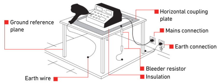
Test setup The product is placed on a table. A grounding plate is positioned next to it. The ESD gun is applied to the product by contact or by approaching it. The discharges are applied in both positive and negative polarity.
7.1.5 How Is the Test Performed?
The device is subjected to discharges at the voltage levels specified in the standard using an ESD gun. Both positive and negative discharges are applied. The discharges are applied to the following points: Metal surfaces User-accessible plastic surfaces Keypads and buttons Connector areas Exposed screws
The product operates in normal functional mode throughout the test, and its behavior is observed.
Number of discharges Generally, ten discharges are applied to each test point. Each discharge is repeated in both positive and negative polarity.
7.2 EFT Burst Test – IEC 61000-4-4
This test measures immunity against fast transient burst pulses. It evaluates the device’s resistance to very fast and repetitive electrical noise generated by switching loads. It is a mandatory immunity test within the scope of CE for all commercial products.
7.2.1 Purpose of the Test
It verifies that the device can continue to operate without malfunction under the following conditions: Relay or contactor switching disturbances Fast pulses radiated from motor drives Disturbances generated by switched-mode power supplies Transient noise present in industrial environments
In short, it tests whether the device can continue operating on a noisy mains supply.
7.2.2 Which Devices Is It Applied To?
The EFT test is applied to all devices with AC or DC power lines. Additionally, depending on the product standard, it may also be applied to the following lines: Data cables and input/output lines Control lines Communication lines
In summary, EFT/Burst is applied to the ports and cable types specified by the applicable product or generic standard; having a power cable alone does not determine the complete test plan.
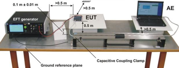
7.2.3 Test Environment and Setup
The test setup provides the following functions: It couples EFT pulses to the product It prevents noise generated by the product from returning to the mains
Setup rules
- The table height is eighty centimeters.
- An insulation layer is placed under the ground reference plane.
- The cable length is one meter.
- The product is kept in normal operating mode throughout the test.
7.2.4 How Is the Test Applied?
The EFT generator produces fast transient burst pulses. These pulses are injected into the power line via the CDN. The behavior of the product is monitored in real time.
At each level, the device is tested for at least one minute and observations are made.
What Is a CDN (Conducted Disturbance Network)?
Coupling networks: EFT/Burst uses a coupling/decoupling network or capacitive clamp as specified by IEC 61000-4-4. Surge uses a dedicated coupling/decoupling network defined by IEC 61000-4-5. Conducted RF immunity (IEC 61000-4-6) uses a CDN, current clamp or electromagnetic clamp depending on the cable and test configuration. These networks are related, but they are not interchangeable.
7.3 Surge Test – IEC 61000-4-5
This test is an immunity test against lightning effects and mains surges. The surge test measures how resistant a device is to high-energy pulses and is the most critical among immunity tests.
In real life, these pulses occur due to lightning strikes, switching events on the mains, large loads being switched on and off, and disturbances in industrial power lines.
These pulses are much slower than those in the EFT Burst test but have much higher energy. Therefore, this is the test with the highest likelihood of causing physical damage to products.
7.3.1 Which Inputs Is It Applied To?
Applied mandatorily:
AC inputs
DC inputs, especially externally powered devices with 24 V and above
Large wired power lines
Generally not applied:
Low-voltage signal lines
If testing is required for these lines, a special coupling network is needed.
7.3.2 Test Levels
Typically used levels:
Line to Line (L–N): 1 kV Line to Earth (L–PE or N–PE): 2 kV
For industrial devices, this level can go up to 4 kV.
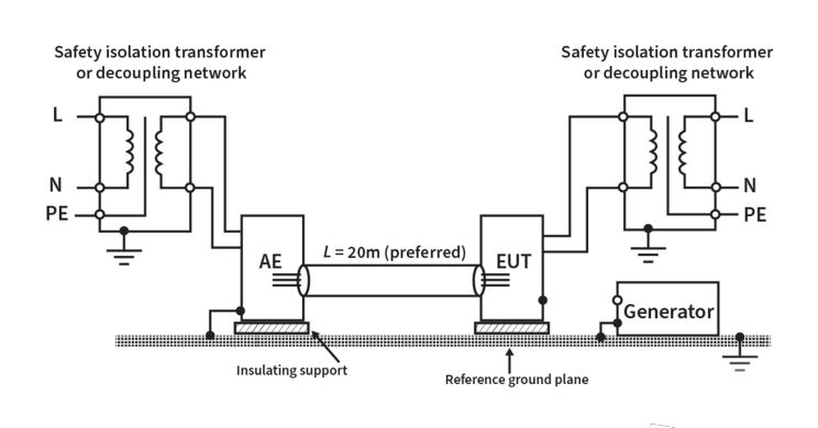
7.3.3 Test Environment and Setup
The surge generator is connected to the product via a CDN, that is, a coupling decoupling network. The product is positioned on a table at a height of eighty centimeters. A ground reference is present. The cable length is set to one meter.
7.3.4 How Is the Test Performed?
A positive surge pulse is applied to the device. A negative surge pulse is applied on the same line. It is repeated on both Line to Neutral and Line to Earth lines. Five to ten repetitions are applied at different levels. The behavior of the device is continuously monitored.
The surge test is the immunity test with the highest potential to cause physical damage to the product. Incorrect selection of MOV or TVS diodes usually leads to failure during this test.
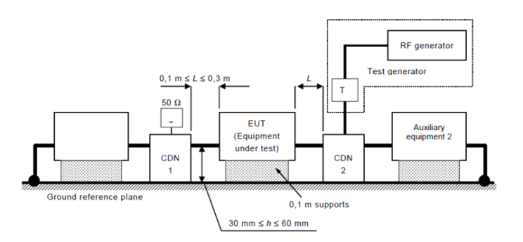
7.4 Conducted RF Immunity – IEC 61000-4-6
This test measures a device’s immunity to radio frequency signals injected via cables. The RF signal is applied to the cable, and it is evaluated whether the device can continue to perform its functions under these conditions.
7.4.1 Which Devices Is It Applied To?
It is applied to relevant AC- or DC-powered devices and to signal/data ports when the applicable product standard identifies those cables as test ports. The presence of a cable is a practical reason for the test, but not by itself a universal applicability rule.
• Ethernet
• RS485
• Sensor cables
• Alarm–security devices
• Industrial control systems
✔ It is also mostly applied to devices powered by wall adapters (the adapter cable carries RF).
❌ Which devices is it not applied to?
→ It is not applied to mini devices that contain no cables and are completely wireless.
Examples:
• Small power banks
• Simple flashlights powered only by batteries
• Small wireless toys with a single PCB
Because: RF signals are injected via cables → if there is no cable, the test is not meaningful.
7.5 Radiated RF Immunity (IEC 61000-4-3) (Radiated RF Immunity Test)
Is the device resistant to radio frequency (RF) signals present in the environment? This test measures whether the device can continue to operate when exposed to electromagnetic fields (radio frequencies) applied through the air.
7.5.1 Which Devices Is It Applied To?
Except for special cases that are out of scope within CE, it is applied to almost all devices except the following:
• Completely mechanical products
• Passive products (resistors, cables, plugs, etc.)
• Some special devices with very low power consumption (if specified by the product standard)
7.5.2 Test Environment
Radiated RF Immunity testing must be performed inside an anechoic chamber.
Basic setup:
• The device is placed on a table at a height of 80 cm
• The antenna is positioned in front of the device
• The antenna tests in both horizontal and vertical polarization
• The device is rotated 360° and scanned from all angles
• The RF signal is gradually increased while the device is monitored (operating display, functions, communication)
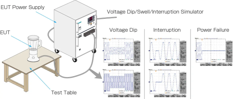
7.6 Voltage Dips, Short Interruptions and Voltage Variations (IEC 61000-4-11) Voltage Dips, Short Interruptions and Voltage Variations Test
7.6.1 What Is This Test Performed For?
In real life, mains electricity is not always stable.
• When loads such as air conditioners, motors, or ovens are switched on, the voltage drops
• When elements such as fuses, relays, or contactors switch, sudden voltage dips occur
• Short-duration power interruptions may occur
The device must not collapse, must not be damaged, and must continue to operate safely under these conditions.
7.6.2 Which Devices Is It Applied To?
Very simply:
Applicability is defined by the product or generic standard. In general, IEC 61000-4-11 is used for AC-powered equipment connected to public low-voltage networks, while DC-powered equipment may be evaluated under IEC 61000-4-29 when applicable.
❌ Not applied to:
• Devices operating only with DC (IEC 61000-4-29 is applied to these devices)
7.6.3 Test Environment
Mains → Dips / Interruptions Generator → EUT (Device)
8. Summary
In this section, we summarized the fundamental EMC requirements that a product must meet within the scope of CE in a holistic framework. We explained that emission tests verify the noise emitted by the device into its environment, while immunity tests verify the product’s resistance levels against electromagnetic stresses such as ESD, Burst, Surge, and RF. We emphasized that EMC standards are divided into three main categories—military, automotive, and commercial—and that this article comprehensively addressed only the tests applied to commercial products. We stated that Harmonics, Flicker, Conducted, and Radiated Emission tests determine mains compatibility, while the Surge test is the most critical evaluation step against high-energy pulses. We also noted that A–D performance levels define test results and that Level A and Level B represent acceptable performance according to international standards.
References
- IEC 61000-4-2, Electrostatic discharge immunity test.
- IEC 61000-4-3, Radiated, radio-frequency, electromagnetic field immunity test.
- IEC 61000-4-4, Electrical fast transient/burst immunity test.
- IEC 61000-4-5, Surge immunity test.
- IEC 61000-4-6, Immunity to conducted disturbances, induced by radio-frequency fields.
- IEC 61000-4-11, Voltage dips, short interruptions and voltage variations immunity tests.
- CISPR 32 / EN 55032, Multimedia equipment emission requirements.
- EN 61000-3-2, Limits for harmonic current emissions.
- EN 61000-3-3, Limitation of voltage changes, voltage fluctuations and flicker.
9. Closing
In Part 3, we examine the safety tests applied within the scope of the LVD (Low Voltage Directive). You can write any questions or comments below. Your feedback is very valuable to me, and I will try to answer every question as best as I can. See you next week.